Friday, March 25, 2016

3D Printer

THE FUTURE IS NOW!

I've purchased a 3D printer.  It was a bit of an impulse purchase from Amazon, and by that I mean that I time-boxed the research period before purchasing.  If you do any web searches for 3D printers, there is a TON of information out there and a lot of it is difficult to internalize without any 3D printing experience.  So, I decided that ~$400 was a price point that I could handle for a toy that might be awesome or may turn out to be a flop.

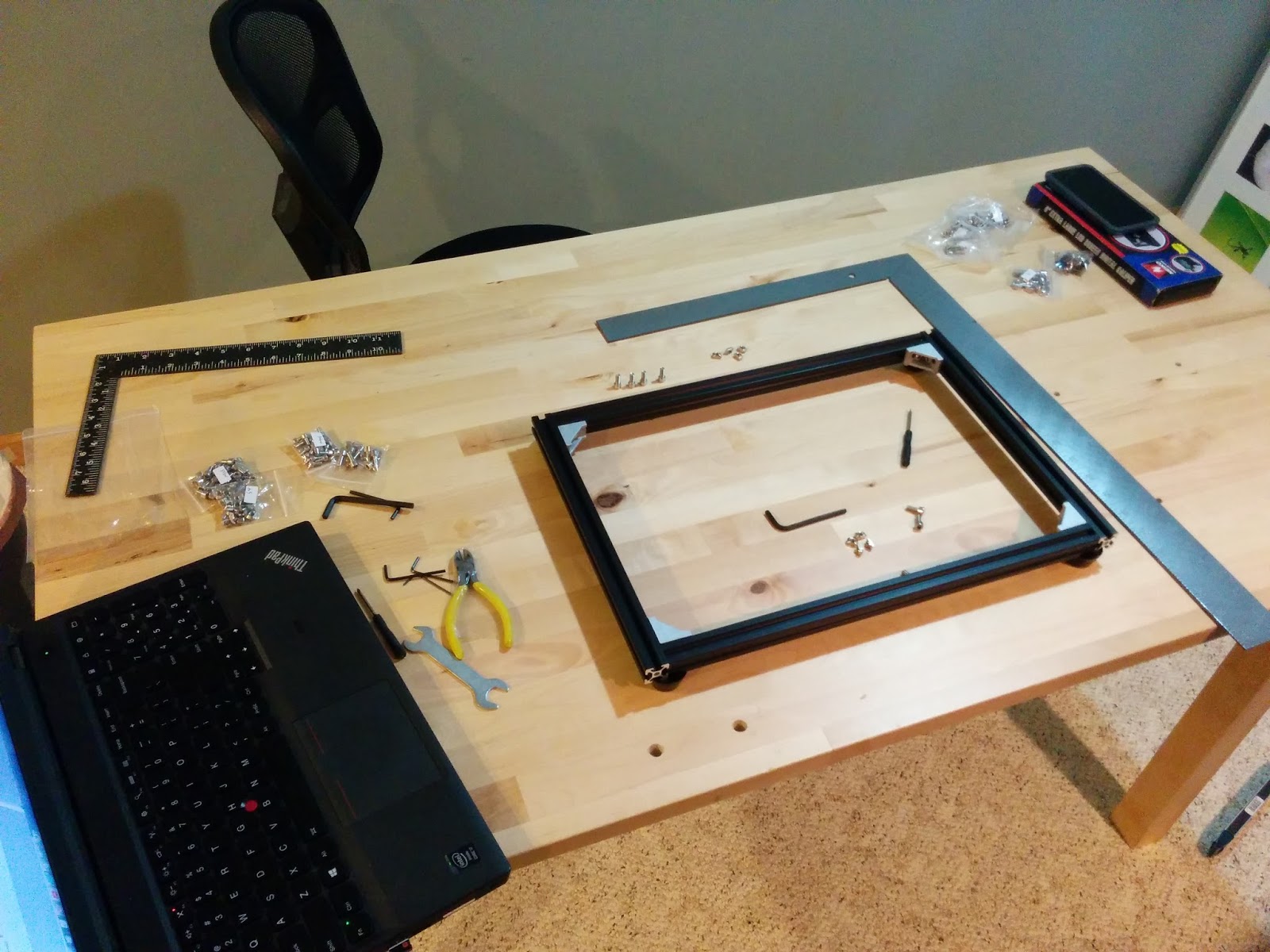
With the $400 option, there is some assembly required.  When I say "some," I mean "a ton."  Here's what it looks like out of the box:

I asked one of my grad school buddies if he wanted to lend a hand with the assembly.  His response was something to the effect of "You better not start without me!"  Two engineers should be able to throw this thing together on the quick, right?  A Saturday morning should do the trick, right?  Wrong.

Here are some photos of the assembly process:


One minor setback occurred when I failed to correctly identify a stepper motor.  The kit includes two different sized motors, just a few millimeters different in length.  The z-axis motors are slightly shorter and, as we learned, the taller stepper motors don't fit.


As the wiring came together, it slowly devolved into an absolute rat's nest.  Although it's a bit unsightly, I prefer this slightly less polished model of printer because I can easily trace lines, troubleshoot, and replace individual components.


Throughout the course of the build, I was surprised with the relatively high level of quality for a kit straight from China.  The installation instructions were in poorly translated English and weren't always accurate, but it possible to figure it out with a little deduction.

My quality opinion went down when I realized that I was short five fastening parts.  They're sort of like M5 nuts, but with a special shape that allows them to turn 90 degrees and then stop within the aluminum frame channel.  I contacted the seller through amazon and they said they will ship me the missing parts.  Since I didn't want to wait for the slow boat, I improvised for the mean time:


There's nothing a little duct tape can't fix!  Well, nothing except this protruding set screw that prevents the extruder heatsink from seating properly...


Fine, there's nothing a little duct tape, a drill press, and a step bit can't fix!


Next, I got those blasted cables under control... zip ties!


And, finally, a test print:


Saturday, February 27, 2016

First IoT Gizmo: Enhanced

I know what you're probably thinking after reading this post title: "How could it possibly get any better?"

I agree.  It's a thing of beauty already, but some parts showed up recently including a 128x64 .96" OLED.  I thought it would be a better value add to visually display the current temperature (and some other data) on the OLED display.

Getting this thing to work with the ESP8266 proved to be a bit of a challenge.

First off, the device's documentation is mostly nonexistent.  Before you can get anywhere with an I2C slave device, you need to know its address.  After using the addresses on the back of the PCB with no success (and some beating my head on the wall), I did some outside the box thinking and found this little gem.  It scans the I2C bus and looks for slaves on every possible address.

After determining that the correct address was 0x3c, I started hunting for a library that let me use this thing without implementing low level code.  Several Arduino libraries for 128x64 OLEDs were available, but they only sort-of worked.  The Adafruit library ran for a little while but it would always crash and cause the ESP8266 to reboot.  Eventually I found this library, which is specifically written for the ESP8266.  The only minor issue was that the code didn't compile, but it was minor so I fixed it, submitted a patch on github, and moved on.

The code I've got so far is worthy of calling a "proof of concept".  It works, but it usually crashes.  I'm 99.9% confident that it's the excessive use of delay(...) calls, causing starvation to things like the WiFi stack.  Before I deploy this thing in practice, I'll probably try running it using a cyclic executive.  This is a perfect use case for timers, but I've not found readily available documentation on the ESP8266 timers.  This is part of the down side of using the Arduino framework on this thing - you have no idea what's actually running under the hood.  More research may be in order here...

Here are some photos of the "proof of concept":


Also, I wanted to get this thing off of my ESP8266 programming board + breadboard, so I whipped up a protoboard version.  Side note: I'm feeling much more confident in my soldering and board layout having made just a small number of these things.  If you haven't moved past breadboards, I would strongly recommend soldering up some permanent boards.  Visuals:


If anyone is interested, here's a schematic of the board.  Note that RST and CH_PD pins on the ESP8266 need to be pulled high in order for it to run.


Saturday, February 20, 2016

First IoT Gizmo

I made my first internet-connected sensor.  I suppose this makes me an Internet of Things expert, right?

While I'm no expert, I did learn a lot along the way.  One of the biggest learnings was how stupid-easy it was to set up a place to dump my data.  I used data.sparkfun.com to publish data "stream".  This freely available platform is based on phant, which appears to be developed by Sparkfun.  Sign up was fast, easy, and didn't even require me to give away all my personal information!

Here's what their UI looks like:

A handy button labeled "Export to Analog.io" produces an ultra-schnazzy chart:


There is a phant library accessible in the Arduino IDE library manager.  I looked into this briefly but determined it to be of little use in the case of ESP8266.  The library looks to be focused on constructing the message payload that you could just send out over TCP port 80, which makes sense if you're running on an Arduino and may have different TCP/IP stack implementations depending on what adaptation gizmo (e.g., ethernet shield, WiFi shield, etc...) you're using to connect it to a network.

Since the ESP8266 features a full TCP/IP stack out of the box and the libraries include a HTTP client, it was easier just to use that.  I was in a rush to see it working, so created data with a GET request.  As a professional software engineer who works in RESTful services, this made me die a little bit on the inside.  I have to keep reminding myself that this is a hobby, and that it's OK to lower my coding standards back down to the undergrad-level of "get it to work."

The gizmo itself consists of an ESP8266 and a 18B20 one-wire temperature sensor.  The 18B20 is much more expensive than the pile of LM35 sensors I had laying around.  Since the ESP8266 has no onboard ADC (well, no ADC that you can use on a GPIO pin), one is forced to use a digital sensor.

This was my first attempt at one-wire interface.  One-wire is a bit of a misnomer because you also need a ground (which in my case was a wire), thereby increasing your wire count to two.  Since the circuitry for parasitic power wasn't work it for me, my wire count was again incremented putting us at three.  Long story short, it worked out just fine.

Here's the gizmo:


Thursday, February 18, 2016

ESP8266 Programming

The ESP8266 is an amazing little unit.  I've had some ESP8266-01 boards on hand for some time now, but haven't had an opportunity to start fiddling with them until recently.  My interest in this board was originally for use as a WiFi enabler for another microcontroller (an AVR), but this article caused me to rethink things.  With a little effort, the ESP8266 can be reflashed to both act as a WiFi device as well as run your logic.

I started out using the hackaday article to build a programmer.  It was a vile, ugly thing.  I didn't go to school for electrical engineering, and it probably shows through in this thing:


It probably goes without saying that this rat's nest of wires didn't work well, so I built a different rat's nest:


The truth of the matter is that the first one didn't work well because I was powering the ESP8266 through my USB-TTL-Serial device.  This device had a convenient 3.3V pin, but it put out nowhere near the current required by the module when it starts talking WiFi.  So, I added a 3.3V power regulator, capable of 800mA, along with a 330uF capacitor to the circuit.  This yielded repeatable results -- much more satisfying than intermittent results.

My third programmer revision was inspired from an article I found when searching for ESP8266 stuff.  This board works reliably and I had the forethought to include headers to supply easy access to GND, GPIO0, and GPIO2.


It wasn't long before I realized that my brilliant forethought to add headers for GND, GPIO0, and GPIO2 forgot to include a pin for VCC.  Thus, it was no longer brilliant and needed an amendment.  Since I was making changes, I added some other improvements to include fancy button label stickers and a stress relief for the wires going to the barrel jack.  Eventually I'll get a female barrel jack that I can solder to the protoboard directly, but this will work for now.  Revised:


For programming the device, I opted to go for the Arduino software with the ESP8266 plugin.  The lack of intellisense and some other professional IDE software features are a bit of a turn off, but it is a free and easy to use option for the time being.  Well, easy to use from a toolchain and device flashing perspective -- not so much coding.


Friday, February 12, 2016

Temperature and Humidity Logger

I was past due for a project.  I had a technical itch that needed to be scratched.

Note the past tense. :-)

Enter the amazing Temperature and Humidity Logger 5000!  The genesis of this project idea stems from my fiance's lasik eye surgery last summer.  With the dry humidity conditions over the winter, she was experiencing painfully itchy eyes.  I got her a humidifier for the bedroom, and I'm curious how effectively it's working.

The project is to log data over time and analyze the humidity and temperature readings.  Who doesn't love some data to analyze?

The parts include:

The general logic is:
  1. read temperature, humidity, heat index
  2. read date and time
  3. append results from #1 and #2 to a file on the SD card
  4. repeat about once a minute
I prototyped everything up using a breadboard and an Arduino Uno clone.  It looked like this:


Once I got this up and running with some [quite frankly hacked together] code [that I'm not the proudest of but this needn't be perfect], I moved forward with making it a little more permanent on a protoboard.  I also downsized to an Arduino Nano clone.  These documents helped to plot out the pin mappings between the Uno and the Nano.

I learned that soldering and physical prototyping are "development areas" for me.  Nonetheless, it came together and it worked.  Here's how it looks:


After a short stint in the upstairs bathroom, I couldn't resist pulling the card and plotting the data.  For those of us who love charts, here's a little eye candy:


Wednesday, January 20, 2016

Code Freeze 2016: LightBlue Bean

I recently attended the Code Freeze 2016 conference at the University of Minnesota.  This year they had a strong slant toward the Internet of Things.

Included in your attendance fee was a LightBlue Bean.  Here are some pictures of the unit.  The LED for size reference--I was too lazy to run upstairs and grab a coin.


The device is designed for the "maker" crowd and, as such, features a sort of built in proto-board at the bottom.  I find that this isn't entirely useful for my needs, as I probably just want to tinker around a bit and not commit to soldering in any sensors or actuators.  I quickly realized this would be of much more utility with some female headers.

The 3V CR2032 watch batteries this thing runs on appear to be another issue I'll run into quickly.  Since I'm hacking up headers, I soldered one on for an external power source at the same time.


This gizmo is set up to operate around 3V, so 3.3V should work just fine as a power source.  I have a new crimper and a bunch of connectors in my parts bin, so whipped up a fancy cable to power the device from my PL-2303HX based USB-TTL adapter.  This particular device has +5V and +3.3V pins--very handy.


Alright, enough with the plumbing.  The real question is "What do I think about this Bean?"  Well, I think it has its pros and cons.

Pros:
  • Small, portable, can run on battery power
  • Has a SoC for Bluetooth Low Energy (BLE)
  • Is programmable over BLE
  • Uses the same MCU (AT328P) as the common Arduino Uno
  • You can program it with your cell phone
  • Has built in RGB LED, accelerometer, and temperature sensor


Cons:
  • Isn't terribly common or popular - lack of support
  • Lacks headers for easy connectivity for beginners
  • Is not really "Arduino Compatible" - it uses a different bootloader, pinouts, etc...
  • It was a real pain in the neck to figure out which pins support PWM output
  • I cannot program it over BLE from my Windows 7 laptop because they have no Windows 7 support
  • The bluetooth device appears not to support the Serial Port Profile (SPP) out of the box, so it's a challenge to get debugging output much past a blinky light
  • The protocol used for programming the device appears to be proprietary
  • The programming from smartphone is kind of a gimmick.  It's difficult to edit code on your phone and you have to use a "cloud compiler"
  • No 802.11x wifi
  • There is a proprietary API to learn (sort of)
All in all, it's a neat device.  I'm happy to play with it if someone gives it to me for free (which they did).  I probably would not buy one of these out of pocket.  There are several other options on the market that I would choose over this, depending on my use case.